Induction motors that won’t start properly
 |
“ Theory:
is when one understands everything,
but nothing works.
Practice:
is when everything works,
but we don’t know why.
Here,
we have achieved both:
nothing works
and nobody knows why.
” |
This is particularly true of induction motors:
wound components, especially motors, have always been a
Black Art to a simple electronics engineer like me - even while I was at university many moons
ago. |
So when my 1967 Hotpoint Supermatic twin-tub washing machine went phutt, was it a case of ditching it and
getting an automatic, or trawling eBay (which I did, out of curiosity - and found a 1986 model going for a
song - but it was in Glasgow - over 500km from where I live)... [20 years or more in production says a
lot...]
Or, since the problem wasn’t terminal and it isn’t bristling with non-replaceable one-chip wonder
electronics - fixing it.
Well, the spinner on this twin-tub goes at 2200RPM - way more than any automatic can achieve - and
I’d have to completely redesign my kitchen to plumb in an automatic. Besides which, I have solar
water heating, so a modern ‘cold water only’ automatic would be an utter waste. And, as I
live on my own, it isn’t used every day.
I decided in the long hot summer of 2018 that all my winter clothes, spare bedding and loads of sweaty
stuff from a recent cycling holiday all needed a good wash, so out came the trusty Supermatic. I was
part way though when the spin dryer started very slowly and wouldn’t speed up. Then it started
emitting smoke....
Fortunately, I shut it off in time, let it cool down and - in trepidation - restarted it, which it did
normally.
I recall this reluctant starting has happened quite a lot - roughly once every 10 starts, so when I’d
got all the washing out on the line I checked for damage. Apart from a lingering smell, all seemed OK -
the resistance of the windings was the same as those on the main wash motor (which is identical except it has
a different mounting arrangement and pulley), and a Megger revealed electrical resistance to chassis was
acceptably high. No shorted turn either, since my LCR bridge recorded similar inductances on both.
Phew!
However, I noted:
1. No capacitor;
2. A strange device that looked like a filter in series with one winding;
3. The two windings had different inductance and resistance.
 Searching on Google, it transpired that what I have are Split-phase Induction Motors - whereby the Main
winding has a low resistance and relatively high inductance - and there is a ‘Start’ winding that
has higher resistance and lower inductance. The ‘filter’ was in fact a relay (right) that
senses a high current in the Main winding when the motor is stationary, whereupon it switches in the Start
winding. Once the motor is running, the relay drops out as the Main winding current reduces. My
problem was this didn’t happen and, had I not acted quickly, the Start winding would almost certainly
have burnt out. This is often the cause of fires in fridges - particularly if a ‘posistor’ had been used
instead of a relay.
There was nothing wrong with the relay - it wasn’t sticking and uses good old fashioned gravity to
drop out.
Induction motors are extremely reliable - no brushes or slip rings to wear out. However, when run
from a single phase supply, they need an additional Start winding that is usually wound 90 degrees out of
phase with the Main winding. The phasing of this also determines rotation direction: once the motor is
running, it generates its own out-of-phase field to keep it going.
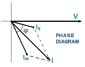
 The problem with split-phase - or ‘resistance start’ types - is the electrical phase difference is
low - usually only 30 degrees - resulting in a lousy stalled torque.
The current in an inductor lags the alternating voltage across it by an angle of tan-1(X/R), where
X is the reactance and R is the resistance (both in Ohms) of the winding. X is given by
2πfL, where L is the inductance (in Henrys) and f is the frequency (of the mains in this
case, ie. 50Hz).
The impedance (Z) is given by √(R2 + X2).
Impedances are often expressed in the form ‘R + jX’ or ‘R - jX’,
where j is a unit vector that incurs a phase shift of 90 degrees.
To all intents and purposes, j is the same as the mathematicians’ i,
which is the square root of -1. But they are technically not identical.
The only way to achieve a sufficient leading current is to insert a series capacitor -
but what value?
The Theory - which doesn’t work:
My LCR bridge measures at 1kHz, 15kHz or 200kHz: none of these is anywhere
near 50Hz, so even readings at 1kHz are not really valid. But it gave an indication.
I measured:
Main: 10.1 Ohm and 56mH
So the impedance is 10.1 + j(2πf x 56m) = 10.1 + j17.6 Ohms
and the phase lag is tan-1(17.6/10.1) = 60 degrees
Start: 24.1 Ohm and 29.3mH
So the impedance is 24.1 + j(2πf x 29.3m) = 24.1 + j9.2 Ohms
and the phase lag is tan-1(9.2/24.1) = 21 degrees
ie. a phase difference of 39 degrees - a little more than I expected, but still insufficient.
I need a lead of 30 degrees (90 - 60).
Enter the capacitor, whose reactance is
1/2πfC (C in Farads); this comes out negative.
To achieve a lead of 30 degrees, the reactance (X) is given by
tan-1(X/24.1) = 30, hence X = 13.9 Ohms (leading, so is in fact -13.9).
We have a lag of 9.2 Ohms, so the capacitor reactance should theoretically be -13.9 - 9.2 = -23.1 Ohms
to overcome this.
The theoretical capacitance required then is 1/(2πfX) = 138μF
- rather high...
Doing the calculations by measuring the DC resistance (R) with an ohmmeter,
and then the current and applied voltage [to derive the impedance (Z) and
thereby calculate X = √(Z2 - R2)] gave an even more ridiculous result.
The Practice - which does:
I removed the motor and used a 24V transformer to apply 50Hz at a low and safe level to both windings - no
risk of nasty electric shocks or burnt out windings. It also allows tests using lower voltage rated
capacitors. However, it was prudent to tie the motor down to stop it waltzing away when it
starts. Inserting a 0.1 Ohm resistor in series with the return (neutral) lead gives an idea of
overall motor current, by measuring the voltage across it.
So I set it all up to trigger an oscilloscope from the source voltage and connected just the Main
winding. The voltage across the resistor lagged by approx. 54 degrees - this is best measured by setting
the timebase and horizontal shift to display one complete cycle, and then measuring the number of divisions by
which the second trace leads or lags. One division is 36 degrees, and I had a lag of 1.5
divisions. Repeating with just the Start winding gave a lag of 29 degrees: a difference of 25
degrees. I wanted a lead of 90 - 54 = 36 degrees (one division). Inserting a 100μF capacitor
(the largest highish voltage one I had) gave a lead of only 0.4 divisions - indicating too low a reactance and
hence too high a capacitance - so the calculated 138μF was way off the mark.
Time for trial and error: the best value turned out to be 60μF.
Anything smaller incurs too much phase lead and too low a current in the Start winding.
So much for the theory...
Now to test it all out with the motor running. With an ammeter in series with the Start winding, and
no capacitor, the motor ran, albeit rather slowly. I noted the current (not representative of the real
world since I was running it at 1/10th its operating voltage). Repeat with 100μF in series: a
somewhat higher current, but the motor ran faster. Repeat with 60μF in series: a lower current than
originally and it ran faster still. 50μF and it ran slower again with a further reduced current.
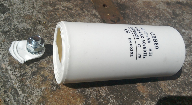
 So I ordered a
60μF start/run capacitor rated at 450V ac. It arrived with its mounting stud broken off.
Bugger!!! I wanted this fixed now, so I decided, since it was electrically OK, I’d keep it
and tie it to the the bottom chassis rail of the washing machine with zip-ties. However, before doing
this...
The start relay will open-circuit the Start winding together with its capacitor, probably on a current zero
crossing point, meaning the mains voltage will be near a peak. So the capacitor could be left with a
hefty charge on it (up to 400V) - which would remain for several hours. Not at all safe, so please,
please fit a bleed resistor of about 22kΩ and 1 watt rating across it.
Doing this will mean it is discharged to a safe voltage within 8 seconds
but have no effect on the improvement we have achieved.

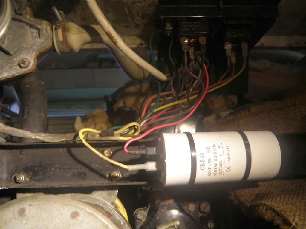
Capacitor as fitted (viewed from beneath). Note: the yellow wire is the motor Start winding
and the extra red wire from the capacitor goes to the relay left bottom terminal.
Result: perfect starting every time. And also, with an ammeter in series with the whole lot, the
start current spike was so short, its needle never overshot. Previously, overshoot was noticeable, even
on a normal start.
BTW - the main tub motor has an identical starting arrangement, but it never has been sluggish to start -
probably because it is quite severely geared down.
Washday blues over!
Steve Glennie-Smith 19th July 2018
Back

 Searching on Google, it transpired that what I have are Split-phase Induction Motors - whereby the Main
winding has a low resistance and relatively high inductance - and there is a ‘Start’ winding that
has higher resistance and lower inductance. The ‘filter’ was in fact a relay (right) that
senses a high current in the Main winding when the motor is stationary, whereupon it switches in the Start
winding. Once the motor is running, the relay drops out as the Main winding current reduces. My
problem was this didn’t happen and, had I not acted quickly, the Start winding would almost certainly
have burnt out. This is often the cause of fires in fridges - particularly if a ‘
 The problem with split-phase - or ‘resistance start’ types - is the electrical phase difference is
low - usually only 30 degrees - resulting in a lousy stalled torque.
 So I ordered a
60μF start/run capacitor rated at 450V ac. It arrived with its mounting stud broken off.
Bugger!!! I wanted this fixed now, so I decided, since it was electrically OK, I’d keep it
and tie it to the the bottom chassis rail of the washing machine with zip-ties. However, before doing
this...