There was an old fashioned rotary dial phone in this house when I moved in. That was in pre-BT days when the GPO had the monopoly on the British phone system and, in addition to paying line rental, you had to rent the phone itself as well! When deregulation came, I told BT (as it had become by then) I didn’t want to continue to rent this obsolete pile of junk (as I considered it to be at the time) - and went out to buy a shiny new push-button thingy. All fine, except the electronic attempt at a ringer it produced drove me nuts...
BT never asked for the old phone back (I’d almost certainly paid for it many times over), so I trotted it out just to have a bell again. Then, several years later, I found they were becoming ‘collectable’ (though not worth megabucks, even today - there are loads of them on eBay, and you can buy cheap Chinese copies from the likes of Amazon).
What I have is a type 746 - the GPO’s last offering that had a proper bell (listen here) - and precursor to that awful Trimphone, which was as light as a feather (so it waltzed round the table as you dialled it) and a dreadful warble that some birds could mimic (was that the phone - or another pesky magpie?)
Yes, it’s clunky - but actually extremely well-made and definitely over-engineered. And, above all, it’s very simple and reliable. Though in these days of DTMF push-buttons, ancient dial phones baffle some of today’s kids - as this hilarious video shows!


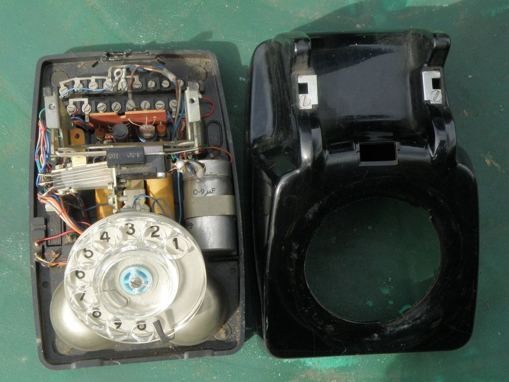
As an engineer, I was curious to see what went on inside. Moreover, by now I had a problem with my broadband occasionally dropping out, which I found didn’t happen anything like as often if I disconnected the old girl. There are several circuit diagrams on the ’net, but they’re all in ‘1950s wiring diagram’ style (like this ‘official’ circuit that BT inherited from the GPO), which aren’t at all easy to follow. So I took it apart by unscrewing the single screw at the back (thoughtful design - it is retained once loose) and taking off the cover. A single screw in the centre of the PCB (by the left orange wire in the photo) released it, so I could trace out its circuit.
Although it looks an utter ratsnest inside, it’s not that difficult to find out what’s going on. The grommets holding the handset (left) and line (right) cables have been removed from the central retainer at the back for clarity.
The circuit diagram I traced out is below (click on it to see it in more detail):-
| *1 | Broadband filter added to stop the bell pranging the Internet. Standard links T8<->T9 &
T17<->T18 removed. Standard connections: Dial orange moved T8 to T9; Bell return moved T17 to T18; Line 5 moved T19 to T16. The bell inductance is very high (8.4 Henrys for a 4kΩ bell and 2.6H for a 1kΩ bell). Thus, if a ring pulse ends with current flowing in the bell, there will be a significant ‘inductive kick’ that could upset broadband. This rather crude filter attenuates any spike so formed. |
| *2 | T2A, T19A and T19B are on silkscreen but are not fitted. LK1 and LK2 are bypassed with PC track. |
| *3 | A 3.3kΩ resistor replaces link T4<->T5 to reduce the REN to 1 if used with the earlier
1kΩ bell. (REN means Ringer Equivalence Number, which determines the load put on the ring generator at the exchange. A REN of 1 is equivalent to 4kΩ: most exchanges can drive 4 such loads.) |
| *4 | Shown with handset ON HOOK. GS1B makes before GS1A changes over when the handset is lifted. |
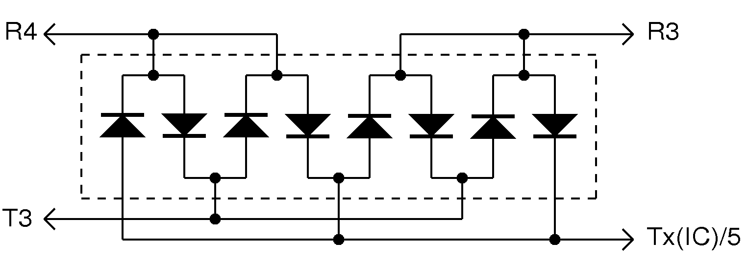
| *5 | Marked as ‘Regulator’ in old GPO diagrams. MR1 (the green thing that looks like a 9-legged caterpillar in the photo above) is laid out as a diode stack:  The ‘Regulator’, which also incorporates R3, R4 and RU1, is a separate item in the earlier Tele 706. MR1 and MR2 are selenium disc rectifiers - NOT silicon. (The purpose of MR2 is to prevent ‘Acoustic Shock’ - ie. not having your ear blasted if the switch intended to short out the earpiece while dialling failed to do so.) |
| *6 | C1/2 and link T6<->T7 were not fitted to latest Tele 746s (Tele 8746), when the bell capacitor was fitted
as standard in the master LJ box. Intermediate 746s (as above) had a 4kΩ bell and one 900nF
capacitor for C1/C2. The bell impedance in early Tele 746s (and 706s) was 2* 500Ω/1.3H. These units had two 900nF or a single 1.8 |
The Dial
All rotary dials (except those subsequently modified for Tone Dialling) use the Pulse (or Loop Disconnect) system. Dialling is achieved by rapidly opening and closing a switch according to the number dialled (once for a ‘1’, twice for a ‘2’ etc. up to 10 times for a ‘0’). The rate at which this switch is opened and closed is defined within fairly close limits: this is necessary to ‘tell’ the exchange it is receiving a dialling signal instead of the line simply being repeatedly hung up. The rate is set fairly high to prevent cheating by manually tapping the off-hook (as was attempted to avoid payment in the old ‘Button A and B’ phone boxes). Speed regulation is achieved by using a mechanical governor, a miniature version like that used to control speed of a stationery steam engine. The dial return spring pressure is geared up to rotate the governor via a worm drive. It works by two small weights constrained within a housing: as speed increases the weights fly outwards until they touch the housing, whereupon friction slows it down. By barely touching the housing, equilibrium and thus a constant speed is attained. The gearing up includes a clutch to allow dialling up (ie. winding up the spring) not to be impeded by the governor.

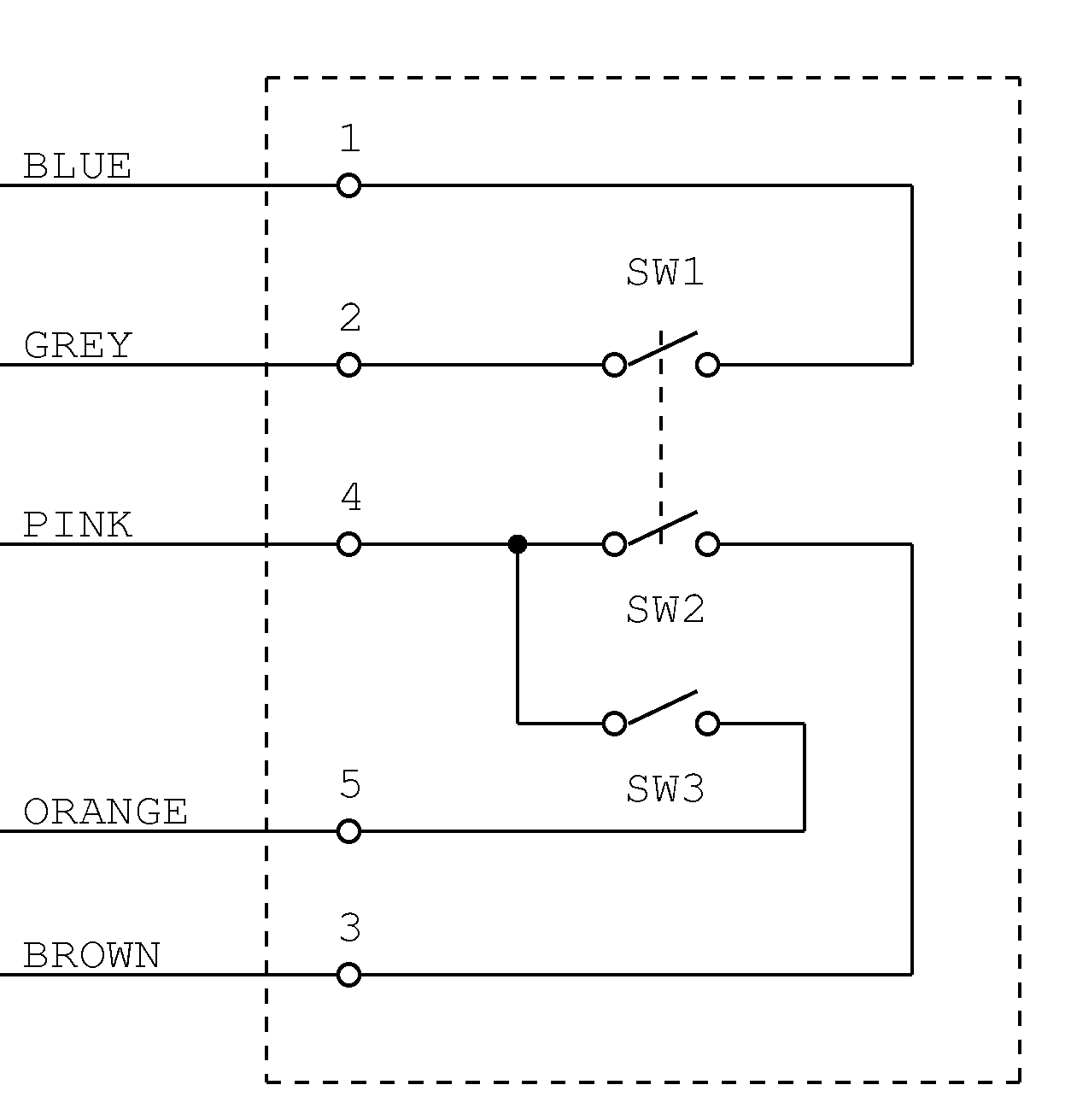
The Loop Disconnect switch (SW3 - refer to circuit diagram right of Dial No. 21) is closed when the dial is at
rest. Additional switches (SW1 and SW2) short out the microphone and earpiece respectively whilst
dialling, to prevent dial pulses deafening the user...
The inventor of this was one Almon Brown Strowger, an undertaker in late 19th century Kentucky. An amusing anecdote about Strowger, who also invented the first automatic exchange, is that the wife of a rival firm of undertakers, who worked as a telephone operater, was diverting calls away from Strowger’s business to that of her husband. Strowger sought to cut out the ‘middle person’ with his invention, in 1889, of an automatic exchange. He patented it in 1891 - the same year that he attained a patent for the rotary dial, which has changed very little since.
The dial is the most complicated part of an old phone, and it is fair to say that the plastic version is the only part of a 706/746 that is under-engineered. Failures I have encountered are:
- The small body that retains the fixed end of the wind-up spring is retained by a pathetically small segment of nylon located beneath the central wheel. This breaks off, leaving no spring tension;
- The end of the governor near its worm drive pops out through a slot in the main body, so it disengages completely from its bearings.....
- ....which causes the dial to spring back suddenly and break the end-stop peg.
If any of these happen, they can be fixed as follows:
- Sacrifice a scalpel blade by heating it up and gently pushing it through the nylon body (which it will melt in the process). Repeat heating as necessary until sufficient stands proud of the spring on one side and to bear up against the bush on the other. Snap off excess blade;
- Refit the governer and gently melt the two sides of the slot together to prevent this recurring;
- Drill and tap an M3 hole where the peg was and fit an M3 * 6mm countersunk screw in its place. Ensure the screw head is flush under the dial wheel to ensure no fouling.
Wire colours and connections
| Connection | Wire Colour | Dial Tag Number |
|---|---|---|
| SW1/1 | BLU | 1 |
| SW1/2 | GRY | 2 |
| SW2/1 | BRN | 3 |
| SW2/2 & SW3/1 | PNK | 4 |
| SW3/2 | ORN | 5 |
The Tele 746’s predecessor - the Tele 706
 This is broadly similar - the main differences are:
- The cover’s fixing screws are via metal plates that are part of the handset cradle (not a single screw at the rear);
- The cover had no carrying handle (because the GPO didn’t like people carrying them!) But later, a full-width plastic bar that matched the case colour and spanned both the fixing screws, thus serving as a carrying handle, was made available as an option. These are still readily available;
- Earlier models (as the photo, left) had no PCB: the ‘regulator’ was a plug-in item, and it was even more of a ratsnest inside;
- The original dial finger wheel was metal. Later plastic wheels matched the case colour, but these dials were replaced with dial no. 21, with a clear plastic wheel (as fitted to 746s), when a phone was sent back for refurbishment (as had happened at some point to the phone shown left).
Future-proofing a Tele 746 (or any other rotary phone)
When the first electronic exchanges (System X) were introduced, dialling using DTMF (Dual-tone multi-frequency) tones replaced pulse dialling and electromechanics in the exchange. This enabled push-button dialling and additional keys - the ‘#’ and ‘*’.
BT continued to support pulse dialling with its electronic exchanges, and still does so at the time of writing, but this is not guaranteed forever. So, at some point in the future, rotary phones might not be able to dial out. From my point of view, this isn’t a big deal - they’re a pain to use - and it’s all too easy to mis-dial. Let alone no speed-dialling or last number redial... Plus, all this repeated disconnecting the line is a recipe for upsetting broadband. So I keep my 746 only for its bell and to receive calls, which it will continue to do - ensured by an REN of 1, courtesy its 4kΩ bell.
There are at least two manufacturers dedicated to ‘future-proofing’ a rotary phone - by converting its pulses to tones. This is done in one of two ways: either by inserting a box between the phone and the line (Old Phone Works - [USA]), or by fitting a gizmo inside the phone (Rotatone) - the supplied box is wired between the dial and the rest of the phone, which requires a bit of work with a soldering iron. Neater, but a purist would say the phone was no longer ‘original’. Extra features some of these include are: last number redial; ability to dial a ‘#’ and ‘*’; and a limited number of speed dials. These are usually invoked by pulling the dial round as usual and waiting a second or so before releasing it.
