A Master Socket is where the telephone wires come into your premises:-
 |
This is often an LJU2/1A, (or more recently an NTE5). (left: outside and inside views) |
 |
| (right - its circuit diagram) | ||
| NB: This and the input wiring to it is BT’s property, and they get very
upset if you do anything to it. However, since deregulation, you are free to plug extension wiring and your own telephones as you wish into its output socket. |
The LJU (Line Jack Unit) type of socket and its associated (and now - ubiquitous) BT 431A/631A plug (see wiring and colours) were introduced in the early 1980s to facilitate this. Although new installations now use type NTE5 (which was introduced in the 1990s to make user-addition of extra phone sockets even easier), there are still plenty of LJU master sockets around.
The capacitor was needed for some earlier telephones that didn’t incorporate one of their own, for
the bell: it blocks the line DC, but passes the AC ringing current. The resistor (known as the
‘out of service resistor’) simply ensures the capacitor is charged to the 50V line voltage such
that if a Tele 746 or similar is plugged in, its bell doesn’t ‘ding’. The spark gap is
a protection against excessive line voltages, such as might be induced by lightning. It is debatable
whether it could provide much protection - and some think its presence upsets broadband. However, I
doubt the latter: its capacitance is immesurably low, and certainly much less than capacitance between the
lines back to the exchange, so I would prefer to leave it in place.
However, later versions of the NTE5 doesn't incorporate any of these extra components.
Note the BT  logo at the bottom right of the LJU
faceplate (this might be the later ‘piper’ logo on newer sockets). If there is no recognised
BT logo on the master socket, it is ‘unapproved’, meaning if a BT (or now Openreach) technician
finds it, he/she could get waspy....
However, this has been somewhat superseded since Openreach divorced from BT, and the advent of the NTE5 range of master sockets. Although most NTE5s have the word ‘Openreach’ and/or their logo on them, not all do - but Openreach branded NTE5s are readily available anyhow. So, although not recommended, the consequences of fitting a cheapie from Amazon are not as dire as they once were.
Extension sockets are supplied by BT and others: these continue to be LJU types and may fitted by home owners. They may or may not have a logo. The capacitor, resistor and spark gap are not fitted.
The LJU nomenclature is of the form LJUx/yA, where x and y are defined below:
| x | |
|---|---|
| 1 | 55mm square surface mounted box. All wiring is on the backplate. |
| 2 | 67mm square surface mounted box. |
| 3 | 85mm square box, same size as a single standard electrical box. Can be flush-mounted. |
| 4 | Same size as LJU3, but with two sockets for separate lines. |
| 5 | Same size as LJU3, but with two sockets in parallel for one line. |
| 6 | A single socket intended to be incorporated as part of equipment. |
| Only the first three will normally be encountered in a domestic situation. Other configurations exist, up to LJU11, but are uncommon. | |
| y | |
| 1 | A Master Socket, including bell capacitor and resistor, with surge arrester (spark gap). |
| 2 | A Master Socket for PABXs, including bell capacitor but no resistor or surge arrester. |
| 3 | An Extension Socket, with no extra components. |
| 4 | As Master Socket type 1, with screw terminals instead of IDC (Insulation Displacement Connector) forks. |
| 5 | As Master Socket type 2, with screw terminals instead of IDC forks. |
| 6 | As Extension Socket type 3, with screw terminals instead of IDC forks. |
| Not all combinations of the above are available. |
For example, the LJU2/6A is an extension socket with screw terminals in a 67mm square box.
The ‘A’ suffix indicates the mating plug is type 431A or 631A (qv).
An LJU2/3C ‘left-handed’ extension socket is
available for specialist applications to accommodate plugs type 430A and 630A (qv).
The NTE (Network Termination Equipment) socket
Sometimes known as ‘CTE’ (Customer Termination Equipment), the NTE5 range of Master Sockets has been used in new installations since the 1990s. The fundamental difference between these and the LJU range is they come in two parts: one of these terminates the incoming cable, while the other is removable by the customer for connection of extension sockets etc. Thus there is a demarcation: the ‘fixed’ part belongs to the telecom company and must not be tampered with. The removable part can be wired to directly by the customer. All types fit the standard 85mm square standard electrical box; either surface mounted or recessed.
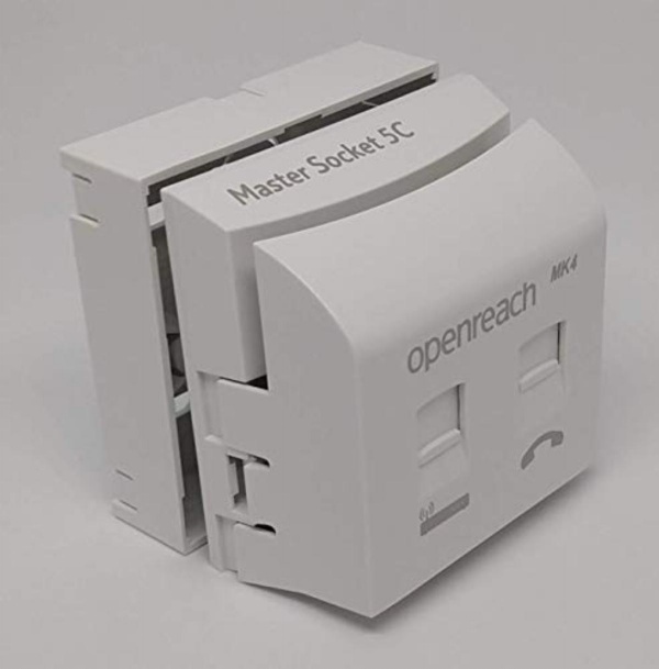
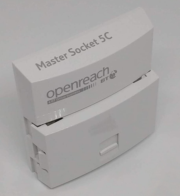
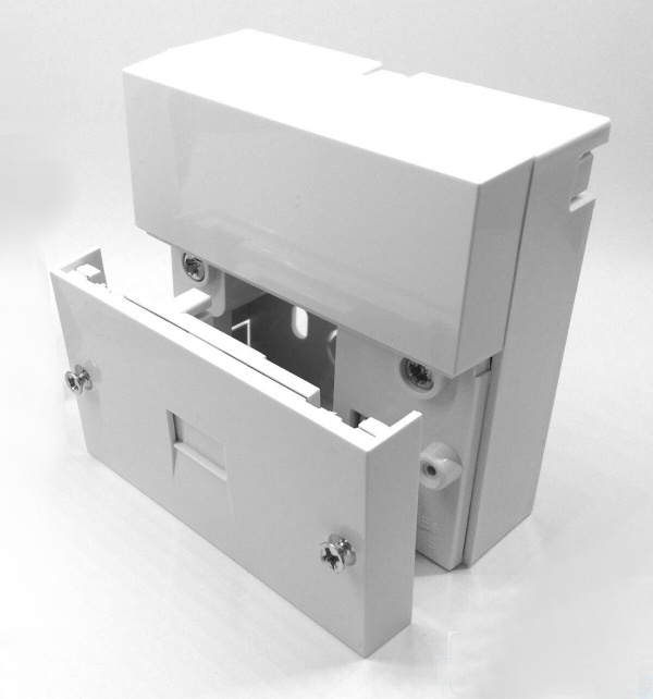 The earlier NTE5A
type, whose customer section is retained by screws, is shown near right. The later NTE5C (middle
right) has a curved front and a clip-on customer section. The NTE5B is similar to NTE5A but there is no
socket on the outside of the customer section.
The removable section can be a simple ‘431A’ socket, or can incorporate a broadband filter (far right), in which case there will also be an RJ11/12 socket (qv.) for the modem. These can be very bulky, risking damage from vacuum cleaners, furniture being moved, etc. The extra weight can result in the clip-on bit becoming - errm - unclipped...
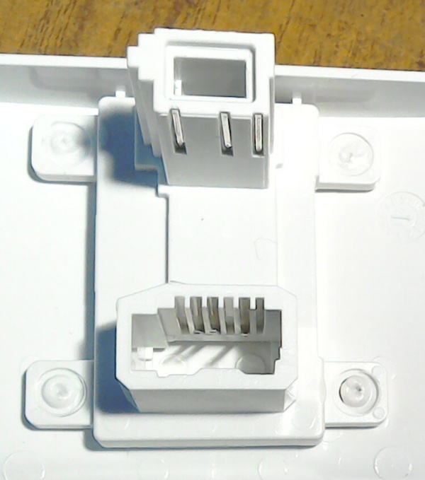
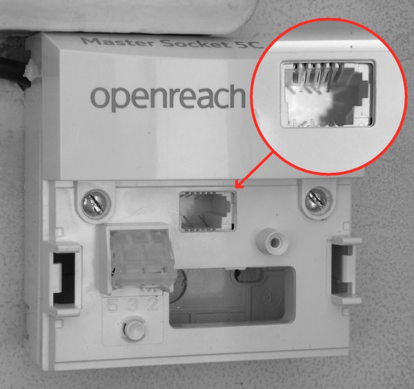 Removal of the customer section reveals a ‘Test Socket’ (shown in detail, near right), used for
troubleshooting. This also isolates all downline equipment and wiring. Note the enlarged socket
area, into which the customer section (rear view, far right) is plugged, which connects through to customer
wiring via the 3 pins at the bottom of the top section (this part plugs into the test socket).
Both sections allow for hard-wiring via IDCs, similar to those in the LJU boxes above. The NTE5C employs the tool-less (and almost foolproof) ‘cam-lock’ type, into whose hinged section the wires are poked and the plastic cam is pushed down onto the IDC prongs. The incoming cable (sometimes called the ‘drop wire’) connects to the rear of the telco's section, so not visible in the photo (near right): it should not be touched. Fixed wiring to sockets can be connected similarly to the ‘cam-lock’ connector, which is to the left of the test socket in the photo. Only pins 2, 3, and 5 (see below for more info) can be connected. The idea behind this is such wiring can be brought in from behind the telco section through the knock-out hole below the ‘cam-lock’ for a neater job, though it’s difficult to see how this could be achieved without removing that section form the backplate.
Note that fixed wiring thus terminated will also be isolated when the front panel is removed. This complicated arrangement makes it ‘safer’ electrically, but the increased number of connections could possibly slow down broadband. So the old LJU master box is, in my view, overall a better arrangement.
If there is a fault (eg. crackly line or slow broadband), plug a known good telephone or router into the test socket. If the fault is still there, it is likely to be outside your premises, so contact your telecom provider to get Openreach out to sort it (you can’t call out Openreach yourself). If the fault disappears, you have a problem with your own wiring which either you sort out yourself or pay Openreach a large sum of money (~£100) to do it for you. The following section on cabling might help you to fix it yourself.
Early NTE5s incorporated a bell capacitor, resistor and surge arrester. These have since been omitted.
Standards? Which standard would you like, Sir???
Ever since there have been telephones there have been multiple ‘standards’ for wire
colours. Things got even more confusing when the BT 431A/631A plug and its associated LJU boxes were
introduced. Then along came the modem and third party phones, which used the American RJ11 or RJ12
connector between the various phone parts instead of having it all hardwired together.
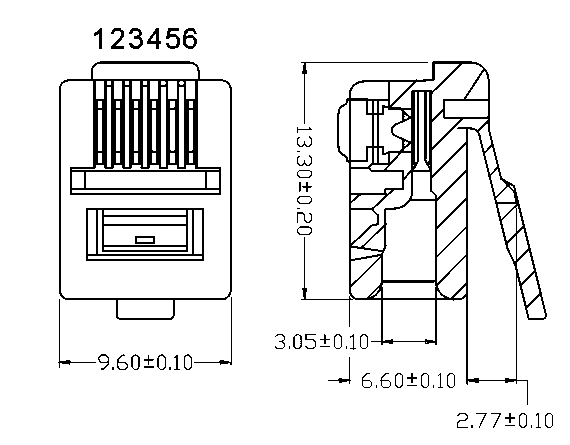
BT and BSI (bless ’em) even managed between them to reverse the pin numbering of the 431A/631A
connector...
 |
 |
| BT 431A/631A plug pin numbering | RJ11/12 plug pin numbering |
... So throughout this article I am keeping to the way the LJU boxes are numbered, ie. pin 1 of the 431A/631A plug is nearest to the release lever. The received wisdom for numbering the RJ11/12 is that pin 1 is on the left when viewed with the pins towards you (ie. the latch away from you) and the cable going downwards. This is how pins are numbered in the drawings above.
If a 431A to RJ11 cable is laid flat, the pins should all be on the same side of the cable, so since pins in the 431A are numbered R↠L, this results in one-to-one pin numbering. However this does, of course, mean that a male 431A to male 431A cable where all pins are on the same side will reverse the connections. There are too many of these around....
To add to the confusion, a variant (430A/630A) of the 431A/631A exists, which has the release lever the other side (shown dotted in the diagram above). Pins should be numbered per the 431A, ie. pin 6 is nearest the lever side (according to this image of the mating LJ2/3C ‘left-handed’ socket). However, reverse numbering (ie. a complete mirror image of the 431A/631A) is often found. This plug was originally intended to connect handsets to phone bodies, but the smaller RJ11/12 types are now almost always used instead.
So what are these various connectors?
The system is designed around a flat cable with a maximum of 6 conductors laid side-by-side. The BT 431A is simply a 631A with the outside pins missing. Pin numbering starts at 2 to maintain some kind of consistency... These connectors are intermateable.
Likewise, the RJ12 has all ways populated and is intermateable with the RJ11, which only uses the middle 4 (or middle 2 for modems). The smaller RJ10, which has a maximum of 4 ways, is sometimes used. Although strictly speaking the pin numbering of an RJ10 is from 1 thru’ 4, for the purposes of this article, pinning is the same as an RJ11 numbered 2 thru’ 5
A better convention for describing these RJ (registered jack) connectors is of the form mPnC, where m is the number of ways and n is the number of pins used - eg. 6P4C is an RJ11.
Do not get these confused with the RJ45 (or 8P8C). This is a wider 8-pin connector used for ethernet
and LAN.
Its latch is wider than the RJ10/11/12, so they are not intermateable.
The following table is an attempt to sort out this mess:-
| Function | Rsvd | Line A | Earth | Bell | Line B | Rsvd |
|---|---|---|---|---|---|---|
| BT431A/631A pin number | (6) | 5 | 4 | 3 | 2 | (1) |
| Numbering is R↠L in BT431A/631A connectors, hence decending numbering in this table. | ||||||
| RJ11/12 pin number (phone) | (6) | 5 | 4 | 3 | 2 | (1) |
| Pins not used in 431A and RJ11 connectors are shown in brackets. RJ connectors are only used at the telephone instrument end of the cable: pin numbering is L↠R in these. | ||||||
| RJ11/12 pin number (modem) | nc | 4 | (5) | (2) | 3 | nc |
| Perversely, some phones use modem connections (extra pins are shown bracketted). Clearly a phone designed for one system will not work with a cable designed for t’other, so it’s always safer to use the cable supplied with the phone... | ||||||
| BT flat flexible cables | BLK | WHI | GRN | BLU | RED | ORN |
| US flat flexible cables | WHI | BLK | RED | GRN | YEL | BLU |
| This coding is often used in imported phones. | ||||||
| 3-wire flat flexible cables | nc | BLU | nc | RED | WHI | nc |
| NB: in all these cases, although the wires within the cable will be in the order stated, these connectors are designed to have the curved side of the cable on the same side as the pins. So if the ‘wrong’ end of the cable is used or the cable is upside down, they will be completely reversed. Wonderful! | ||||||
| 2-wire flat flexible cables | nc | RED | nc | nc | GRN | nc |
|
Short 2-wire cables are often used for the input to broadband filters, usually using the colours shown. But these could be swapped, or any colour pair could be used... | ||||||
| BT Incoming cable | - | WHI | - | - | ORN | - |
| (Auxiliary colour pairs that might be present are:
Black & Green, Brown & Blue and Grey & Red.
Additionally, there are up to 3 steel wires (usually coloured Yellow) that are only used for cable support: they do not carry signals. Be careful: they’re springy steel and can be very sharp! Perversely, the Orange wire is Line B here, but is Line A in the Openreach ‘standard’ for wiring within premises... Older systems used a heavy-duty figure-of-8 twin with no way of telling which wire was which without using a volt meter. | ||||||
| BT fixed wiring within buildings (new(er)) | WHI/GRN | WHI/BLU | WHI/ORN | ORN/WHI | BLU/WHI | GRN/WHI |
| (The secondary colour is usually rings, or could be a tracer,
| ||||||
| Openreach fixed wiring (and GPO pre-1980) | - | ORN | BRN | GRN | BLU | - |
| (The brown and green wires could be swapped.)
| ||||||
| An alternative sometimes encountered... | - | BRN | GRN | BLU | ORN | - |
| I’ve come across this several times. It is not recognised AFAIA, but is much more logical since the Orange wire is Line B - the same as in incoming cables, and the Blue and Green wires are the same colours as their equivalents in flexible cables. Oh well... | ||||||
Wire Functions:
- Lines A & B: These are the lines coming into premises. Line A is the positive, and is connected to earth at the exchange (this means it might be a few volts away from earth at the consumer’s end). Line B is nominally at -50V with respect to Line A when the phone is inactive. The history behind this is telephone lines were powered by float-charged lead-acid batteries so the system would continue to work during power cuts. Backup batteries are usually no longer lead-acid.
- The Bell (or ‘anti-tinkle’) wire: This is not used in modern systems, but when phones with rotary dials that used pulse (or ‘loop disconnect’) dialling and had bells in them, these wires were all connected together to stop dial pulses making bells on other extension phones ‘tinkle’. However, it is still usually connected through within the fixed wiring.
- The bell wire can cause problems if the Line A and B wires get
swapped. Although nearly every phone is polarity insensitive, the bell capacitor is normally connected
to Line B. So if the polarity of a phone further down the line is reversed, the system could end up with
two 1.8
μ F capacitors in series shorting the line, which could easily stop any phone from ringing, muffle speech and qite likely kill broadband. - Even when correctly connected, this wire can slow up broadband, but is very unlikely to do so when only connected on the ‘quiet’, ie. telephone side of a broadband filter.
- Earth: This wire was used in the ‘Party Line’ (or Shared Line) system, whereby
more than one subscriber was connected to a single phone line. Fortunately this was discontinued when a
sufficient number of lines became available for everyone to have their own.
This wire was used to ‘grab’ the line by shorting Line B to earth, which signalled to the exchange a user wanted to make or receive a call.Its other use was ‘Earth Recall’, often used in PABXs.
It required a ‘good earth’ at the consumer’s premises: the system worked because Line A is connected to earth at the exchange.Thus it was important that Lines A and B were not reversed. - It is often connected nowadays for completeness, but has no function.
- Rsvd: The outside pair of wires in a 6-wire system are reserved for PABXs etc, and thus are omitted in domestic setups.
So the bottom line is: in a modern system (ie. just two wires - Line A and Line B - and no bell wire), it doesn’t really matter if these wires get swapped. But in any system incorporating a rotary dial phone with a bell, it is important to get it right. So do so anyhow to avoid any hassle in the future.
Clearly this plethora of colour schemes can easily cause confusion, but provided there is consistency thoughout the system (ie. a particular coloured wire always goes to the same pin number) it doesn't make any practical difference what colours are used - except not keeping to one of the ‘standards’ above will cause major headaches for anyone else who deals with your telephone system!
Extensions
With the advent of the ‘LJU’ system, any number LJU boxes can be daisy-chained in parallel around a house. There is, however, a limit on the number of phones that may be connected at any one time. This is imposed by the exchange on ringer impedance: if there are too many ringers (or bells) in parallel, only some (or none) will work. Most phone systems allow up to 4, as defined by the Ringer Equivalence Number (REN). A bell impedance of 4kΩ (such as the bell type 59D) represents an REN of 1. The older 1kΩ bells originally fitted to Tele 746s and 706s therefore had an REN of 4, so no further phones could be added. However, a 3.3kΩ resistor may be fitted in series with a 1kΩ bell to use it in a modern system. This brings the REN down to 1 while the bell will still ring. However, that approach would not work with Plan 4 (qv).
Cordless phones usually have an REN of 1 (though it is usually less than this in practice): this is a function of the base unit only, so you can have as many handsets as the base unit will permit and still maintain an REN of 1.
In days of of the Tele 746 and earlier, fitting extensions wasn’t simple - it required an expensive visit by a GPO person to intall them: the default 746 configuration was one hard-wired phone with its 1kΩ bell. To ensure all phones would ring when more were added, a complicated ‘series’ system (known as Plan 4) was devised:
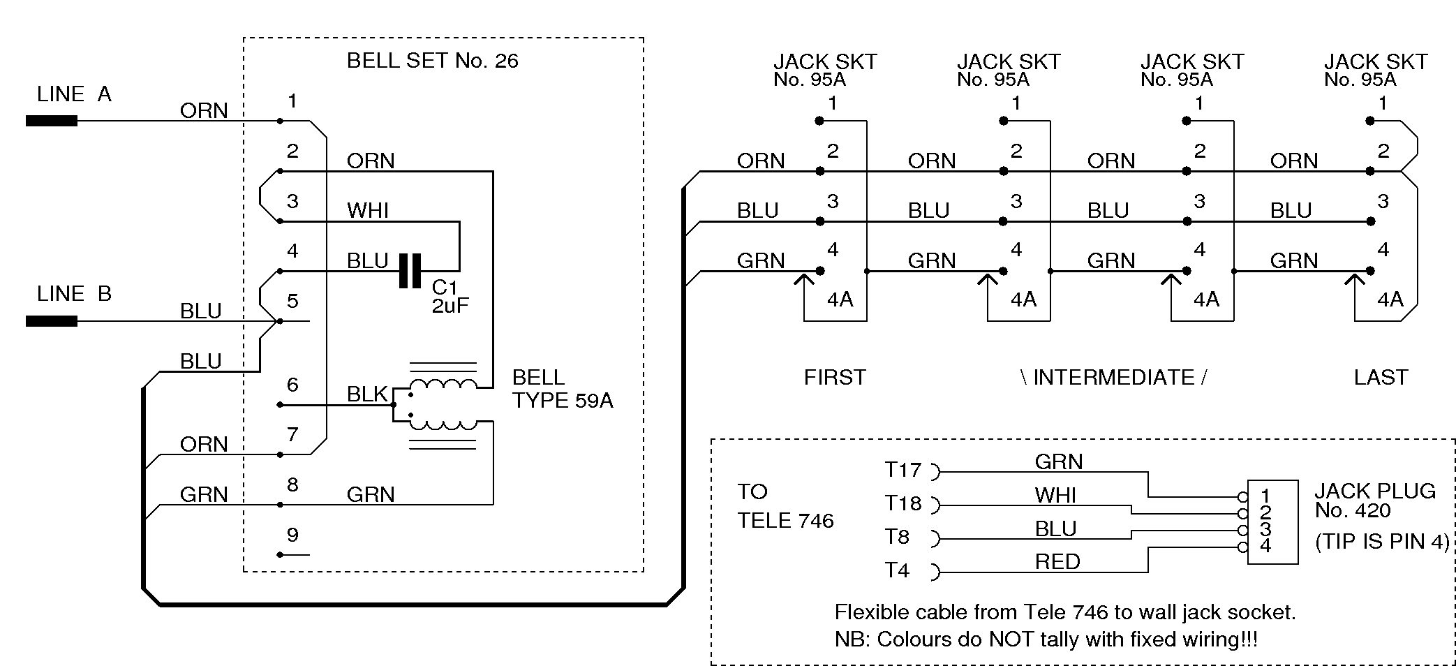
The circuit above is my interpretation of fig. 2 of the dreadfully presented and confusing GPO circuit number N4506. If a phone is plugged into one of the sockets, its jack opens the shorting switch within the socket, which breaks the connection between pins 4 and 4A, and inserts the phone’s bell in series with other bells. If no phone is connected, the bell in the fixed bell set (no.26, which is wall-mounted near the incoming cable), will still ring. Thus additional bells increase ringer impedance, and so do not exceed the permitted maximum REN of 4. The maximum number of phones that may be thus connected is 4.
To add further to the confusing plethora of cable ‘standards’, wire colours in wiring and extension cables differed from each other and from those listed above. Moreover, unlike the convention for most jack plugs, the tip is the highest number.
A 5-pin version is used on shared (‘Party’) lines. In this case, pin 4 is the ‘Party’ pin and the bell link is via pins 5 and 5A.
| 4-pin plug (420) and socket (95A) pin number: | 1 | 2 | 3 | 4 | - | 4A |
| GRN | WHI | BLU | RED | - | ||
| Function: | Bell rtn. | Line A | Line B | Bell | - | |
| Fixed wiring: | GRN * | ORN | BLU | GRN | - | ↓ |
| Terminal 1 is wired internally to terminal 4A | ||||||
| 5-pin plug (505) and socket (96A) pin number: | 1 | 2 | 3 | 4 | 5 | 5A |
| GRN | WHI | BLU | ORN | RED | ||
| Function: | Bell rtn. | Line A | Line B | Party | Bell | |
| Fixed wiring: | GRN * | ORN | BLU | BRN | GRN | ↓ |
| Terminal 1 is wired internally to terminal 5A | ||||||
| * | The Green wires terminate at pin 1 and a different green wire carries on to pin 4 (or 5) of the next
socket in the chain. Other wires carry on through. The Orange wire connects to pins 1, 2 and 4A (or 5A in Party systems) in the last socket of the chain. |
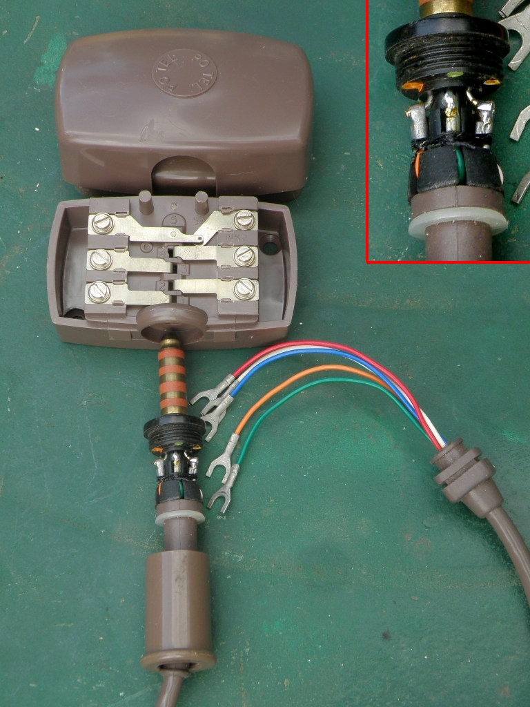
These old connectors and junction boxes were beautifully made:-
 |
 |
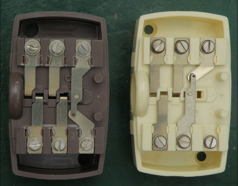 |
| Differences between | ||
| Old hardwired junction box | 5-pin extension jack and socket | 4- and 5-pin jack sockets |
BT8 BT4 The incoming line is connected to the outside pins of the hard-wired box (above left).
BT7 BT3 The terminals are not normally numbered, but on the GPO circuit diagram N846
BT6 BT2 for the Tele 746, they correlate with the junction box photo
BT5 BT1 ← as shown here.
Note the colour coded dots on the 5-pin plug (above centre, inset: 4-pin plug is similar) to facilitate wiring.
You can see from the ‘difference’ photo (above right) that the plastic moulding is the
same for both versions of the socket.
Production engineering at its best!
Steve Glennie-Smith 28th March 2022